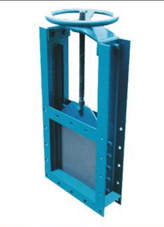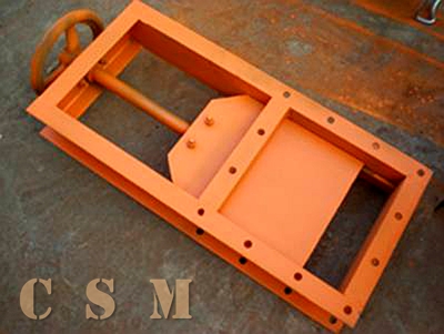
Three Four Ways Chute
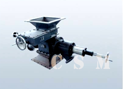
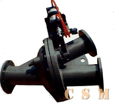
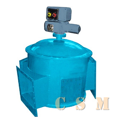
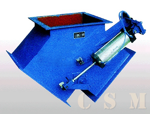
The valve, which is also named splitting machine/ depiler, is widely used in building material, metallurgy, mining, light industry and food industries etc. It is the ideal equipment to change flow direction of solid crystal and powder material in transportation system.
- Structure characteristic:
The splitting machine/ depiler, is welded in fine steel and equipped with different actuators according to the different demands. It has the features of lightweight, antifriction, definite indicating direction, handy switching and flexible operation etc.
Type Ⅰ is side three-way depiler type Ⅱ is face three-way depiler, type Ⅲ is four-way depiler The driving types are five: S denotes manual, D denotes electric, Z denotes automatic, Q denotes pneumatic and Y denotes electric hydraulic.
| Working pressure |
Suitable temperature |
Suitable material specific gravity |
Suitable medium |
| 0.01MPa |
≤300℃ |
≤2.5t/m3 |
Crystal, grain and powder etc |
| Type |
200~250 |
300~400 |
500~600 |
700~800 |
| Electric draw stem |
DTⅠA63-MP:0.06KW |
DTⅠA63-MP:0.09KW |
DTAⅡ100-MP:0.25KW |
DTⅡA250-MP:0.37KW |
| Automatic device |
DKJ-210P:0.025KW |
DKJ-310P:0.065KW |
DKJ-410P:0.16KW |
DKJ-510P:0.25KW |
| Pneumatic draw stem |
10A-5TC50B |
10A-5TC63B |
10A-5TC80B |
10A-5TC100B |
| Electric hydraulic |
DYT100P:0.37KW |
DYT300P:0.37KW |
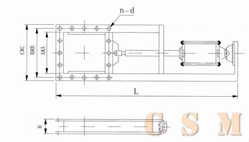
SFC—ⅠAppearance figure
ZFC—ⅠAppearance figure
DFC—ⅠAppearance figure
QFC—Ⅰ Appearance figur
YFC—ⅠAppearance figure
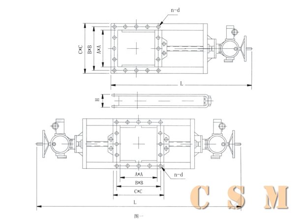
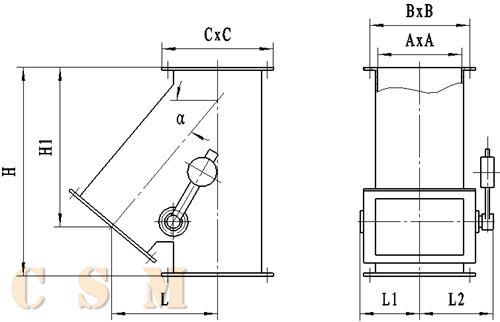
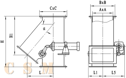
| A |
B |
C |
α |
H |
H1 |
L |
n-d |
L1 |
L2 |
L3 |
L4 |
L5 |
L6 |
| 200×200 |
245×245 |
280×280 |
45º |
530 |
394 |
289 |
8-Φ10 |
180 |
220 |
220 |
290 |
320 |
340 |
| 50º |
600 |
445 |
293 |
| 55º |
650 |
505 |
290 |
| 60º |
735 |
594 |
295 |
| 250×250 |
305×305 |
350×350 |
45º |
605 |
448 |
338 |
12-Φ10 |
220 |
250 |
250 |
310 |
345 |
410 |
| 50º |
675 |
512 |
342 |
| 55º |
735 |
595 |
346 |
| 60º |
820 |
706 |
355 |
| 300×300 |
355×355 |
400×400 |
45º |
690 |
499 |
374 |
12-Φ12 |
250 |
280 |
280 |
375 |
370 |
440 |
| 50º |
750 |
568 |
380 |
| 55º |
820 |
658 |
380 |
| 60º |
910 |
791 |
405 |
| 400×400 |
455×455 |
500×500 |
45º |
825 |
598 |
463 |
16-Φ12 |
280 |
325 |
325 |
425 |
420 |
470 |
| 50º |
930 |
709 |
490 |
| 55º |
1020 |
859 |
504 |
| 60º |
1155 |
1005 |
505 |
| 500×500 |
555×555 |
600×600 |
45º |
1000 |
755 |
575 |
20-Φ14 |
350 |
385 |
395 |
480 |
500 |
520 |
| 50º |
1110 |
888 |
597 |
| 55º |
1250 |
1052 |
632 |
| 60º |
1425 |
1260 |
647 |
| 600×600 |
655×655 |
700×700 |
45º |
1297 |
921 |
706 |
20-Φ14 |
400 |
450 |
450 |
540 |
550 |
570 |
| 50º |
1430 |
1097 |
742 |
| 55º |
1500 |
1223 |
731 |
| 60º |
1677 |
1481 |
768 |
| 700×700 |
755×755 |
800×800 |
45º |
1450 |
1029 |
779 |
20-Φ14 |
450 |
500 |
500 |
630 |
620 |
650 |
| 50º |
1520 |
1163 |
809 |
| 55º |
1708 |
1421 |
850 |
| 60º |
1863 |
1646 |
850 |
| 800×800 |
855×855 |
900×900 |
45º |
1555 |
1125 |
860 |
24-Φ14 |
500 |
550 |
550 |
680 |
670 |
700 |
| 50º |
1702 |
1327 |
907 |
| 55º |
1892 |
1594 |
946 |
| 60º |
2145 |
1885 |
913 |
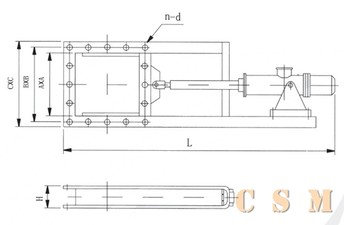
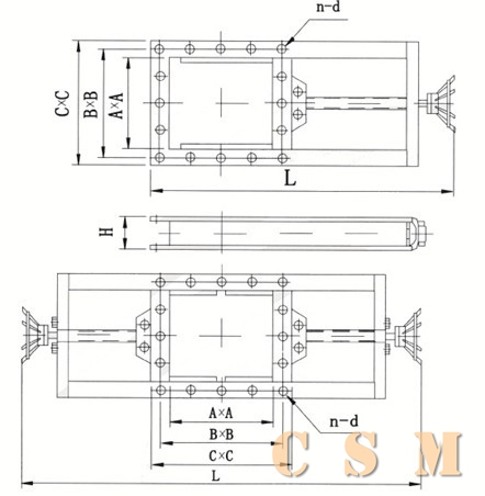
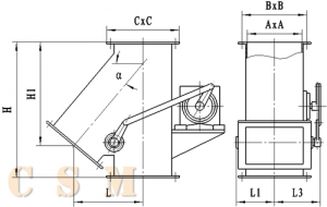
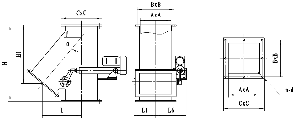
| A |
B |
C |
α |
H |
L |
n-d |
L1 |
L2 |
L3 |
L4 |
L5 |
L6 |
| 200×200 |
245×245 |
280×280 |
45º |
267 |
177 |
8-Φ10 |
180 |
220 |
220 |
290 |
320 |
340 |
| 50º |
282 |
174 |
| 55º |
299 |
161 |
| 60º |
352 |
160 |
| 300×300 |
355×355 |
400×400 |
45º |
322 |
212 |
12-Φ12 |
250 |
280 |
280 |
375 |
370 |
440 |
| 50º |
349 |
209 |
| 55º |
386 |
204 |
| 60º |
431 |
200 |
| 400×400 |
455×455 |
500×500 |
45º |
381 |
251 |
16-Φ12 |
280 |
325 |
325 |
425 |
420 |
470 |
| 50º |
419 |
251 |
| 55º |
448 |
244 |
| 60º |
525 |
245 |
| 500×500 |
555×555 |
600×600 |
45º |
470 |
310 |
20-Φ14 |
350 |
385 |
395 |
480 |
500 |
520 |
| 50º |
532 |
320 |
| 55º |
557 |
290 |
| 60º |
644 |
300 |
| 600×600 |
655×655 |
700×700 |
45º |
502 |
290 |
20-Φ14 |
400 |
450 |
450 |
540 |
550 |
570 |
| 50º |
561 |
310 |
| 55º |
643 |
330 |
| 60º |
738 |
340 |
| 700×700 |
755×755 |
800×800 |
45º |
617 |
380 |
20-Φ14 |
450 |
500 |
500 |
630 |
620 |
650 |
| 50º |
678 |
400 |
| 55º |
795 |
420 |
| 60º |
937 |
442 |
| 800×800 |
855×855 |
900×900 |
45º |
672 |
408 |
24-Φ14 |
500 |
550 |
550 |
680 |
670 |
700 |
| 50º |
763 |
445 |
| 55º |
900 |
482 |
| 60º |
1057 |
493 |
| A |
B |
C |
α |
H |
H1 |
L |
n-d |
L1 |
L2 |
L3 |
L4 |
| 200×200 |
245×245 |
280×280 |
45º |
530 |
394 |
578 |
8-Φ10 |
440 |
580 |
640 |
680 |
| 50º |
600 |
445 |
586 |
| 55º |
650 |
505 |
580 |
| 60º |
735 |
594 |
590 |
| 250×250 |
305×305 |
350×350 |
45º |
605 |
448 |
676 |
12-Φ10 |
500 |
620 |
690 |
820 |
| 50º |
675 |
512 |
684 |
| 55º |
735 |
585 |
692 |
| 60º |
820 |
656 |
710 |
| 300×300 |
355×355 |
400×400 |
45º |
690 |
499 |
748 |
12-Φ12 |
560 |
750 |
740 |
880 |
| 50º |
750 |
568 |
760 |
| 55º |
820 |
638 |
760 |
| 60º |
910 |
741 |
810 |
| 400×400 |
455×455 |
500×500 |
45º |
825 |
598 |
926 |
16-Φ12 |
650 |
850 |
840 |
940 |
| 50º |
930 |
699 |
980 |
| 55º |
1020 |
784 |
1008 |
| 60º |
1150 |
935 |
1010 |
| 500×500 |
555×555 |
600×600 |
45º |
1000 |
730 |
1150 |
20-Φ14 |
790 |
960 |
1000 |
1040 |
| 50º |
1110 |
838 |
1194 |
| 55º |
1250 |
972 |
1264 |
| 60º |
1425 |
1170 |
1294 |
| 600×600 |
655×655 |
700×700 |
45º |
1297 |
921 |
1412 |
20-Φ14 |
900 |
1080 |
1100 |
1140 |
| 50º |
1430 |
1027 |
1484 |
| 55º |
1500 |
1133 |
1462 |
| 60º |
1677 |
1351 |
1536 |
| 700×700 |
755×755 |
800×800 |
45º |
1450 |
1029 |
1558 |
20-Φ14 |
1000 |
1260 |
1240 |
1300 |
| 50º |
1520 |
1128 |
1618 |
| 55º |
1708 |
1311 |
1700 |
| 60º |
1863 |
1506 |
1700 |
| 800×800 |
855×855 |
900×900 |
45º |
1635 |
1125 |
1720 |
24-Φ14 |
1100 |
1360 |
1340 |
1400 |
| 50º |
1702 |
1232 |
1814 |
| 55º |
1892 |
1449 |
1892 |
| 60º |
2145 |
1735 |
1826 |
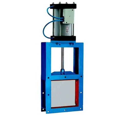
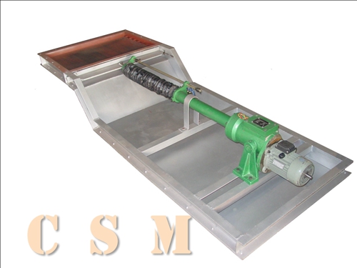
The valve is mainly made up of body, separating plate, transmission shaft, bearing support, sealing, rocker and transmission device etc. Push the heavy hammer of manual valve and switch the flow direction according to the requirement. Command control unit of electric valve power the DT electric draw stem and push the rocker to rotate valve axle in order to switch medium flow direction. The automatic valve is equipped with DKJ electric actuator, which receives and adjusts the control sign of DCS, PLC epistasy meter or manual control sign of operating and outputs angle displacement to drive transmission shaft, then drive separating plate rotating with rocker and valve axle. The open angle of electric actuator and separating plate feeds back 0~10mA or 4~20mA DC signal. Users can control the open angle of plate according to the current signal to adjust the valve. Pneumatic valve is equipped with type 10A-5 pneumatic element and pneumatic draw stem driven by double-control two-bit five-way electric control reversal valve, pushing rocker to drive the axle and plate and switch the flow direction of medium. Electric hydraulic valve is equipped with type DYT electric hydraulic draw stem; it pushes the rocker to drive axle and plate and switch flow direction of medium and meets the requirement of working conditions.
- Transportation and protection
1. Avoid bumping and the valve is in full close in order to avoid damage of disc and driving part.
2.Transmission device and part should be hung up when the valve is in horizontal in order to prevent damage of driving axle.
3. Treatment of dampproof and rainproof should be done to transmission device and part.
4. The valve should be stored in dry room. It should be in full close state when long stored. Add lubrication to the transmission part and the device should be dampproof and dustproof.
- Maintenance and examination:
1.Examine the operating condition of driving part regularly.
2.Replace the lubrication of actuator reducer, lubricating grease of electric draw stem and motor oil of electric hydraulic draw stem regularly.
3.Examine the seal condition of rotate axle regularly. Replace or add graphite stuffing if there is mistake.
4.Examine the plunger joint ring of electric hydraulic draw stem and pneumatic draw stem in order to ensure the normal operation of transmission device.
1. Please indicate the type, model, angle of the valve and technical parameter (using temperature, working condition of equipment and characteristic of medium etc) referring to the product sample when you place an order.
2.Product legend in the sample and actuator code in the form is the basic collocation of our company. If you have especial demand (anti-explosion, outdoors, adjusting type and switch type etc) to another actuator, please refer to the explanation of corresponding actuator code in the sample appendix and indicate it below the basic model.
3.If you don’t indicate actuator code selected by user when you place an order, we will select the basic collocation of our company for you. The basic type is a normal type without any special request and corresponding accessory.
4.If you have other special demand, need special medium or the spec that is not listed in the table, please contact with our department of market and technology. We can design and manufacture for you especially but you must indicate your special demand in the contract.