
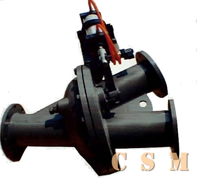
Double-Way transporting Valve
The double valve is widely used in building material, metallurgy, mining, oil chemical, electric power and light industries etc. it is applied in pipe system to transport cement, raw cement, limestone and coal powder with high pressure energy. It is installed on the crotch of pipe to change transportation direction.
- Structure characteristic
The rotating valve plate control the inside changing direction. The adjusting pressure device controls the joint of valve plate and sealing. The outline is like knife-edge so as to remove the clinging on the sealing and ensure the seal performance. The valve has the features of perfect structure, free and reliable direction changing, good gas sealing, endurance, smooth channel and no obstruction. S denote worm wheel drive, D denote electric drive and Y denote electric hydraulic drive.
- Performance parameter
| Working pressure | Suitable temperature | Suitable medium |
| 0.5MPa | ≤200℃ | Coal powder, raw material, cement etc |
- Working principle
The valve is mainly made up of right and left body, rotating valve plate, adjustor, sealing and orientation cam etc. Operate the hand wheel to drive worm wheel, then the handle pole and valve plate will move at the same time, so the valve is in the state of straight through or bypass and the dial shows the position of the valve plate. The driving device drives the control pole and valve plate when it is inputted instruction action, so the valve is in the state of straight through or bypass and feeds back position signal. The orientation cam will drive electric switch and feed back signal when the valve plate is in the position.
- Information for usage
1.Pay attention to the flow direction of medium, which has been marked on the body. The body must be cleaned. Add seal cushion between two flanges connection and screw down the bolt when install the valve.
2.Transporting parts and supporting should be independent from pipe wire and not forced by pipe wire device. Take measure to prevent pipe from expanding and shrinking.
3.Add lubrication to transmission parts and examine the transmission device regularly in the working period of the valve.
SKAppearance joint dimension:
| DN | D | D1 | L | L1 | H | b | n-d | M | G1 | G2 | G3 |
| 125 | 254 | 216 | 759 | 604 | 286 | 20 | 8-Ф22 | 219 | 290 | 320 | 600 |
| 150 | 279 | 241 | 736 | 603 | 273 | 20 | 8-Ф22 | 251 | 310 | 350 | 620 |
| 200 | 342 | 298 | 914 | 781 | 358 | 20 | 8-Ф22 | 318 | 410 | 420 | 630 |
| 250 | 406 | 362 | 1016 | 835 | 432 | 20 | 12-Ф22 | 375 | 440 | 450 | 660 |
| 300 | 482 | 432 | 1169 | 991 | 496 | 22 | 12-Ф22 | 448 | 515 | 550 | 725 |
| 350 | 533 | 476 | 1550 | 1322 | 554 | 22 | 12-Ф26 | 483 | 560 | 594 | 755 |
| 400 | 580 | 525 | 1700 | 1454 | 650 | 22 | 16-Ф30 | 530 | 600 | 645 | 795 |